

Products / Smart Component / Frame Grabber

Smart Component

V5 Series

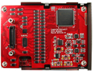
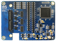
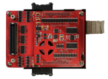
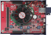
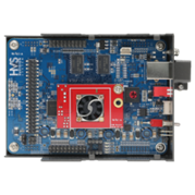
MIPI Image Grabber Board

V5 Series is a core component for industrial machine vision systems, designed to support high-speed image transfer and stable signal processing.

Main Features

MIPI Image Grabber Board

A grabber board that reliably acquires and transfers high-resolution images at high speed for precision inspection of camera modules and core parts such as sensors, lenses, IR filters and AF actuators used in smartphones, tablets, vehicles, drones and robots.

1

MIPI Interface Expertise

Based on years of accumulated MIPI interface know-how, the system provides stable data acquisition and high reliability across various image-sensor environments.

2

Multi Image Grab Support

Multi Image Grab technology processes multiple image data streams at the same time, enabling stable acquisition in high-speed inspection processes.

3

Dual Image Sensor Connection

Connects up to two image sensors or modules simultaneously for parallel image acquisition, improving inspection speed and system efficiency.

4

Precision Sensor Power Measurement

Supports 5-channel and 12-channel sensor power measurement, including standby and dynamic current measurement for sensor-state analysis and stable system operation.

5

Compact Design

Minimizes installation space inside equipment and adapts flexibly to diverse inspection equipment and test environments.

6

Multiple MIPI PHY Support

Supports MIPI D-PHY and C-PHY interfaces, and provides compatibility with various sensor environments through D-PHY / Parallel shared design.

7

High-Speed Data Transfer

Supports 1.5 to 2Gbps per lane and up to 2Gsps per lane for stable processing of high-resolution images.

8

Multiple Cable Interfaces

Supports USB 3.0 cable and optical fiber cable for long-distance data transfer and stable system configuration.

9

High-Performance Buffer Memory

DDR2 and DDR4 (Gen3) buffer memory provide stable buffering performance during high-volume image-data processing.

10

OS Test Support (DCR Board)

Supports OS Test functions based on the DCR Board, making it easier to verify system stability and build equipment test environments.
Specifications

Single supports one sensor connection; Dual supports simultaneous connection of two sensors.


ITEM
V5U_R2
V5U_2G
V5FP
V5FP_Dual
V5FP_Dual_Combo_V1
V5FP_Dual_Combo_V2
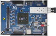
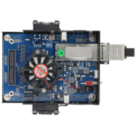
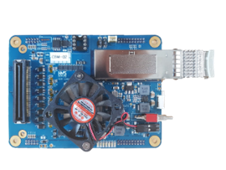
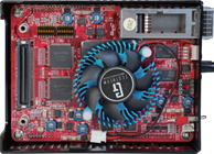
Image
V5U_R2
V5U_2G
V5FP
V5FP_Dual
V5FP_Dual_Combo_V1
V5FP_Dual_Combo_V2
Dimension
114 x 84 x 38.5 mm114 x 84 x 38.5 mm114 x 84 x 39 mm114 x 107 x 39 mm114 x 107 x 39 mm126 x 96 x 39 mm
MIPI Data Capturing 
Rate
D-PHY: 1.5Gbps/LaneD-PHY: 2.0Gbps/Lane
C-PHY: 1.3Gsps/Lane
D-PHY: 1.5Gbps/LaneD-PHY: 1.5Gbps/LaneD-PHY: 1.5Gbps/Lane
C-PHY: 2.0Gsps/Lane
D-PHY: 2.0Gbps/Lane
PC 
Interface
USB3.0PCIe x4 (Gen2)PCIe x4 (Gen2)PCIe x4 (Gen3)PCIe x4 (Gen3)PCIe x4 (Gen3)
Image 
Sensor Interface
MIPI CSI 1/2/4 Lane
MIPI DSI 1/2/4 Lane (Video mode only)
Parallel Interface (Data up to 10bit)
MIPI: 2/4 LaneDual MIPI 1/2/4 LaneDual MIPI D-PHY 1/2/4 Lane
(up to 1.5Gbps/Lane)
Dual MIPI C-PHY 1/2/3 Lane
(up to 1.3Gsps/Lane)
Dual MIPI D-PHY 1/2/4 Lane
(up to 2.0Gbps/Lane)
Dual MIPI C-PHY 1/2/3 Lane
(up to 2.0Gsps/Lane)
Internal 
Buffer 
Memory
DDR2 x 2DDR2 x 2DDR3 x 2DDR4 x 4DDR4 x 4DDR4 x 4
OS Test
Applicable with Mounting DCR BoardApplicable with Mounting DCR BoardApplicable with Mounting DCR BoardApplicable with Mounting DCR BoardApplicable with Mounting DCR BoardApplicable with
Mounting DCR Board
Sensor 
Clock
Programmable Adjust 1KHz to 68MHz (Accuracy: +/-2%)Programmable Adjust 1KHz to 68MHz (Accuracy: +/-2%)Programmable Adjust 1KHz to 68MHz (Accuracy: +/-2%)Programmable Adjust 1KHz to 68MHz (Accuracy: +/-2%)Programmable Adjust 1KHz to 68MHz (Accuracy: +/-2%)Programmable Adjust
1KHz to 68MHz
(Accuracy: +/-2%)
Sensor 
IO Power
Programmable Adjust 1.5 to 3.3V (0.1V step, Accuracy: +/-0.1V)Programmable Adjust 1.5 to 3.3V (0.1V step, Accuracy: +/-0.1V)Programmable Adjust 1.5 to 3.3V (0.1V step, Accuracy: +/-0.1V)Programmable Adjust 1.5 to 3.3V (0.1V step, Accuracy: +/-0.1V)Programmable Adjust 1.5 to 3.3V (0.1V step, Accuracy: +/-0.1V)Programmable Adjust
1.5 to 3.3V
(0.1V step, Accuracy: +/-0.1V)
Sensor 
Power
5Ch programmable power
1.0V to 5.0V
Resolution: 0.01V
Accuracy: +/-0.03V
8Ch programmable power
1.0V to 5.0V, 0.01V step
Accuracy: +/-1%
Each module can use 4Ch power
12Ch programmable power
1.0V to 5.0V, 0.01V step
Accuracy: +/-1%
Each module can use 6Ch power
12Ch programmable power
1.0V to 5.0V, 0.01V step
Accuracy: +/-1%
Each module can use 6Ch power
12Ch programmable power
1.0V to 5.0V, 0.01V step
Accuracy: +/-1%
Each module can use 6Ch power
12Ch programmable
power 1.0V to 5.0V, 0.01V step
Accuracy: +/-1%
Each module can use 6Ch power
Current Measurement
5Ch / 2 types
Standby current up to 2mA
Dynamic current up to 400mA
5Ch / 3 types
Standby current up to 500uA or 5mA
Dynamic current up to 400mA
8Ch / 3 types
Standby current up to 500uA or 5000uA
Dynamic current up to 400mA
12Ch / 2 types
Up to 500uA / 5000uA / 1000mA
12Ch / 2 types
Up to 500uA / 5000uA / 1000mA
12Ch / 2 types
Up to 500uA / 5000uA / 1000mA

DCR Board (Optional)

ITEM
For V5U series & V5FP
Only for V5FP-Dual
Only for V5FP-Dual-COMBO
Image
V5U series and V5FP DCR Board
V5FP-Dual DCR Board
V5FP-Dual-COMBO DCR Board
General Feature
· Sensor Interface: MIPI 1, 2, 4 Lane
· Open / Short Test
· Leakage Current Test
· Sensor Interface: MIPI 1, 2, 4 Lane
· Open / Short Test
· Leakage Current Test
· Sensor Interface
- MIPI D-PHY 1, 2, 4 Lane
- MIPI C-PHY 1, 2, 3 Lane
· Open / Short Test
· Leakage Current Test
Open / Short Test
· Source: Constant Current (0.5 to 3mA / 256 steps)
· Measure: Voltage (0 to 1.8V / 1024 steps)
· Quantity of Test Pin: 24 pins
· Source: Constant Current (0.5 to 3mA / 256 steps)
· Measure: Voltage (0 to 1.8V / 1024 steps)
· Quantity of Test Pin: 54 pins
· Source: Constant Current (0.5 to 3mA / 256 steps)
· Measure: Voltage (0 to 1.8V / 1024 steps)
· Quantity of Test Pin: 54 pins
Leakage 
Current Test
· Source: Constant Voltage (0 to 3.3V / 1024 steps)
· Measure: Current (0 to 2mA / 1024 steps)
· Quantity of Test Pin: 24 pins
· Source: Constant Voltage (0 to 3.3V / 1024 steps)
· Measure: Current (0 to 2mA / 1024 steps)
· Quantity of Test Pin: 54 pins
· Source: Constant Voltage (0 to 3.3V / 1024 steps)
· Measure: Current (0 to 2mA / 1024 steps)
· Quantity of Test Pin: 54 pins
DCR Board 
Interface
· O/S and leakage pin control: SPI
· Source and measure: I2C
· O/S and leakage pin control: SPI
· Source and measure: I2C
· I2C

Application

Camera Module Inspection System

Camera Module Inspection System

Precision inspection of camera modules and optical lens quality in production lines
Mobile Device Manufacturing

Mobile Device Manufacturing

High speed image acquisition for smartphone and tablet assembly process control
Semiconductor Inspection Equipment

Semiconductor Inspection Equipment

Ultra-precise wafer and die-level defect detection for semiconductor fabrication
Optical Module Test System

Optical Module Test System

Functional testing and performance validation for optical communication modules
High-Speed Machine Vision Inspection

High-Speed Machine Vision Inspection

Real-time defect detection at production speeds with multi-lane imaging support
Automotive Vision Inspection

Automotive Vision Inspection

Automated visual quality control for automotive components and body surface analysis
CONTACT